HW 25/22
The Use of Hollerith Punched Card Equipment in Bletchley Park
Ronald Whelan M.B.E.
| |
The text of this article is copied, with permission, from the UK National Archives document HW 25/22. The document appears to have been written in the 1990s, given the mention of "50 years since work in B.P. came to an end". Ronald Whelan sadly died in September 2000, aged 86. Added editorial notes are formatted like this to distinguish them from the original text. |
Contents
- 1 Introduction
- 2 Hollerith Equipment Used in Hut 7 / Block C
- 3 Staffing
- 4 Maintenance and Engineering Personnel
- 5 Machine Modifications
- 6 Operating Instructions
- 7 Customer Liaison
- 8 Shift Working
- 9 The Hollerith Card and Coding
- 10 Card Punches and Verifiers
- 11 The Sorter
- 12 The 405 Tabulator
- 13 The E6/6 Tabulator
- 14 The Reproducer
- 15 The Collator
- 16 The Decimal Cross-footing Multiplying Punch
- 17 Group Repeat Search
- 18 Processing of Naval Enigma Traffic
- 19 The Window Index of Key Groups
- 20 Positional Double Repeat Search
- 21 Production of Difference Tables
- 22 Index of Column Differences
- 23 The Work Range and Personnel
- 24 The Visit of Winston Churchill
- 25 Drayton Parslow
- 26 Conclusion
1 Introduction
In May 1940 the initial installation of Hollerith punched card equipment was made in Bletchley Park. The installation consisted of the following machines:
- a) E6/6 Tabulator
- b) Horizontal Sorter
- c) Card Reproducer
- d) Non-electric Key Punch and Verifier
Some work for Colonel Freddie Jacob and Mr. W. Bodsworth had already been done by The British Tabulating Machine Co. in Letchworth, the work being carried out within Mr. F.V. Freeborn's Department. When further processing was called for it was decided that this should be done at Bletchley Park, by personnel from B.T M., the team consisting of Freeborn, my brother Norman Whelan and myself. The equipment was housed in a small hut outside the perimeter fence, but when extra work was to be done the installation was moved into Hut 7, within the main compound.
The range of facilities given by this initial set of equipment was limited, especially since the E6/6 Tabulator did not provide for alphabetical character printing. Although B.T.M. marketed some tabulators providing for a limited span of alphabetical printing they were not suitable for work at B.P. However, some years previously B.T.M. had obtained an I.B.M. 405 Tabulator, this having an alphabetical/numerical printing span of 43 positions on the left of a print-line with a 45 numerical figure span on the right hand of the line. The 405 employed the superior 4-zone character punched hole code as against the 3-zone coding then in use on B.T.M. machines. Knowing that B.T.M. still held the 405 Tabulator in cold storage, arrangements were made for it to be installed in Hut 7.
Following this arrangements were made early in the war for a large number of 405 Tabulators to be shipped direct to B.P. When unpacked it was generally found that gifts of food supplies had been enclosed in the large crates, giving us among other items our first introduction to Spam.
In the paragraphs which follow an attempt is made to give some idea of the features and uses of the various Hollerith machines which we used at Bletchley Park. However, as it is 50 years since work in B.P. came to an end some of the activities which took place in Hut 7 / Block C, together with details of equipment used and the exact numbers of staff employed have not remained in clear perspective, and many details have faded beyond recall.
2 Hollerith Equipment Used in Hut 7 / Block C
- Model 20 Key Punches and Verifiers
- Electric Alpha/Numeric Punches and Verifiers
- E6/6 Tabulators
- 405 Tabulators
- Horizontal Sorters
- Reproducing Punch Machines
- Card Collators
- Decimal Cross-footing Multiplying Punches
- Plugboards
- With the exception of the Sorters and the Key Punches and Verifiers, all other machines required the use of plugboards. The plugboard controlled the functions of the input cards, providing great flexibility in the range of work which could be undertaken. The plugboards were of the detachable type. Many were retained permanently plugged for repeated use.
3 Staffing
Following the setting up of the initial equipment in Hut 7 the work load increased rapidly, so that additional staff had to be found, as well as the installation of further equipment. Two experienced key punch operators were obtained from a London Hollerith contract as a beginning. In addition two young men from Freeborn's Dept., (Mr K. Primett and Mr G.T. Hardy) joined our team, together with a third, Mr. R. Allen, who was released from the Navy, all three becoming key members of the establishment throughout the war. To provide for the very large number of additional punch and machine operators who were needed, recruitment was made of local girls, these being trained in house. At a later stage in the war a great increase in operating strength came when a large complement of WRNS personnel was drafted to us, in addition to a contingent of 20 University Graduates.
4 Maintenance and Engineering Personnel
Some time after the start of our operations the B.T.M. Company allocated a resident maintenance engineer to service the equipment. Later on he and others were placed on permanent assignment within Hut 7. With the further growth of the installation personnel were seconded from the R.A.F. (selection being made by Freeborn) and trained in-house to service the equipment. This training was carried out by the B.T.M. engineers.
5 Machine Modifications
With ideas initiated by Freeborn the B.T.M. engineers devised some non-standard circuitry and devices as additional features on some machine. These modifications increased the work range and simplified some operating procedures. Details of these changes were not made known to B.T.M.
6 Operating Instructions
Over the course of time standard procedures were evolved for the machine operations necessary to achieve specific results, e.g. production of a Difference Table or a Window Index of Key Groups. These operating instructions specified the sequence in which the various operations were to be carried out, the plugboard set-ups which were necessary, to be made by the operator, or by means of permanently wired plugboards. Nowadays such instructions might be called a program - at the time the typed working instructions were simply called a "Write-up". The permanently wired plugboards were identified by letter/figure tags, e.g. "I/l" identifying Indexing plugboard set-up No. 1.
Very frequently an urgent job requirement would arise in the morning, a procedure would be devised and master cards punched during the day shift, for the processing to be carried out on the evening and/or night shift.
7 Customer Liaison
We had many processing tasks which were carried out on a regular time basis, daily, weekly or monthly. But a great deal of our effort was devoted to runs made on a once only basis. With these, good "customer liaison" was essential to get a clear understanding of the requirement, and some customers, though brilliant in their sphere, were less than coherent in explaining the problem and what was required to be done.
8 Shift Working
For operating on a 24-hour basis the operating staff were divided into 5 teams, each headed by a Team Leader who was responsible for some 20 machine operators, and who also had overall responsibility for a support team of around 12 punch operators, although each punch-operator team was under the direct charge of a Punch Supervisor.
Three of the five teams worked during the day shift, another the evening shift with the fifth team working the night shift. The change over was made on Saturday, which meant that no team was present on Saturday morning. But if cover were required at that time the work was dealt with by the "management staff". (It was always necessary for some work to be under way at that time in order to keep to the schedule for the Enigma processing for Hut 8).
As well as providing the continuous round the clock operation the five shift system gave operators three consecutive weeks of the preferred day time work and also one long weekend in five.
9 The Hollerith Card and Coding
The cards are of manila stock, being 71/8 inches in length by 31/4 inches, having a corner cut at the top right hand end. Along the bottom edge the numbers 1 - 80 identify 80 columnar positions.
| |
Most sources give the dimensions of IBM-standard 80-column cards as 73/8" x 31/4". This source explains that size was chosen for the original Hollerith cards in 1890 so as to use storage boxes intended for US banknotes. |
Each column can be utilised to record a digital value or a letter by means of a punched hole for a digit, or a pair of holes for a letter in the twelve available punching positions in a column. The 12 punch hole positions in a column from top to bottom are known as Y, X, 0, 1, 2, 3 ... 9 index levels. A single hole in a column in one of levels 0 - 9 obviously stands for the digital value so marked; a pair of holes in a column being used for alphabetical recording, where a "Y" hole in combination with any of 1, 2, 3 ... 9 stands for the letters A, B, C ... I; whereas an "X" hole in combination with 1, 2, 3 ... 9 gives letters J, K, L ... R. For the remaining letters of the alphabet a "0" hole in combination with 2, 3, 4 ... 9 gives letters S, T, U ... Z. In the alphabetical coding given above the "Y", "X", and 0 holes are said to be "zone" designators and the code as a whole is said to be a 4-zone code, three zones having been used for the letters A to Z, but the numerals alone are held to stand as a fourth zone. The "X" hole standing alone in a column can have a further function in that it is used as a designator to mark a card as a master card, carrying data to be transferred to detail cards, or to call a data distribution mechanism into operation.
10 Card Punches and Verifiers
Although the Model 20 Punches and Verifiers were used initially at B.P., card punching output was greatly improved by the use of electrically powered machines, which eliminated card handling for the insertion and ejection of cards, and their stacking. It is perhaps true to say that at our peak we had at least 20 electric automatic punches and the same number of electrically operated verifiers. A few manually operated machines were retained for general use in making the occasional replacement of a damaged card.
11 The Sorter
On this machine cards fed from the hopper at a speed of 400 cards per minute, for each card to be distributed into one of thirteen pockets, according to the positional value of the punched hole in the column being read by the sensing brush. Cards were normally fed from the hopper with the "9" edge leading. A card sensed with a "9" hole travelled the length of the machine to fall into the left-most (9) pocket, the pockets from left to right being labelled 9, 8, 7, 6, 5, 4, 3, 2, 1, 0, X, Y, R, R standing for reject for cards having no punched holes in the column.
Unless dealing with a large quantity of cards, sorting normally commenced with the "units" column of a field, with the units 0 to 9 sequence of cards re-fed to the machine to deal with the "tens" column, and so on.
Where over large files of cards were to be sorted a start was made with a so-called "Break-down" sort. In this the high-order column of the field was sorted first, to divide the file into sub-sets, 0, 1, 2, etc. The advantage of this was the smaller quantity of cards to be handled in sorting on the remaining columns of the field in dealing with each breakdown sub-set, and/or that a number of Sorters could be employed by sharing the sub-sets among them. This was done when completion of all processing for a given task was a matter of urgency.
In the alphabetical 4-zone sorting of cards it was necessary to carry out two sorting runs per column, the first to segregate the cards by the zone punchings, 'Y', 'X', and '0', and then to sort each zone batch of cards by the numeric components 1, 2, ... 9 of the characters to obtain the alphabetical sequence.
The standard Sorter was equipped with a device known as the commutator. This had 12 sliding switches in its circumference, these switches corresponding to card levels 9, 8, 7, ... 0, X, Y. If a switch was set to its off position the current supply to the sensing brush contact-roll was cut off at the corresponding index point in the card cycle. Thus, if switches 9, 8, 7, ... 1 were set "off" only the zone punchings, 0, X, Y would be read.
However, the operators were taught not to zone sort by use of the commutator device, as constant manipulation of its switches was time consuming, but perhaps more importantly it could be wearing on the operator's finger-nails. Instead operators were taught to carry out the zone sort by feeding the cards to the machine with the "Y" edge of the card leading, so that either Y, X, or 0 holes would be sensed before the numeric component of a letter, ensuring that the card would enter the intended "zone" pocket. Each Sorter was equipped with a Sorting Tray, mounted in a convenient placement above the machine. The tray had 13 vertically arranged compartments each of about 2000 card capacity and corresponding to the 13 pockets of the Sorter. As a sorter pocket tended to become full the operator transferred the cards to the appropriate compartment of the tray. Before doing so a check was made to ensure that a mis-sort had not occurred. This was done either by sighting light through the appropriate column/hole position, or by entering a "sorting needle" through that position.
12 The 405 Tabulator
| |
See also this description of the IBM 405 Alphabetical Accounting Machine. |
The machines were delivered to B.P. to the full specification for analytical and accounting procedures, which meant that there were many features which we seldom, if ever used. But such features could be regarded as part of our resources, which could be drawn upon if we needed to devise a procedure to cope with an unusual demand upon our services.
Apart from its use for print-outs of such items as Window Indexes, and the daily listing of the tetragraph repeats located in Enigma message processing, Difference Tables and message decrypts, its counter facilities for addition provided for making frequency counts. Interfold stationery was used for all print-outs, the number of lines printed per sheet and the numbering of the lines was controlled, if required by a special non-standard device. This was designed and engineered by our two chief resident BTM engineers. They called this device the SNAP LINE device, without giving explanation for the nomenclature. However, the code name SNAP was not difficult to decypher given that the name of one engineer was Aspinall, the other Page, and the fact that the device could serially number the print lines if required, as well as effecting ejection of the form on attainment of a specified number of lines
13 The E6/6 Tabulator
The specification for this machine was variable in accordance with the user's needs. The machine used at B.P. was equipped with five counters, each of nine adding wheel capacity. The print unit provided for seven "banks" of type bars. Each of the five print banks to the right of the print unit was permanently linked to the corresponding counter unit to enable a total held in the counter to be printed. The two left hand print banks could be used for indicative printing only. But all seven print banks could be used for listing data read from each card passing the card reading brush station, whether counter addition applied or not.
As with all types of tabulator the E6/6 provided for two modes of operation:-
- i) Tabulating (150 cards per minute)
- ii) Listing (100 cards per minute)
When operating in the tabulating mode the print unit came into operation for the first card of a group of cards to print the indicative data for that group. The subsequent cards of the group then passed at tabulating speed for the summation of values, or for card counting, card feed ceasing for totals to be printed when the first card of the following group had been detected by the control unit.
All types of BTM and IBM tabulators were equipped with two 80 column card reading stations, known as the Upper Brushes and the Lower Brushes. A card feeding from the hopper encountered the Upper Brushes first before being read at the Lower Brush station.
The Lower Brushes were used to read data for listing and also for adding by the counter units.
As a card was read by the Lower Brushes the following card was read by the Upper Brushes to allow readings from successive pairs of cards to be evaluated by a Control Unit, which had capacity to accept readings from up to 16 card columns. The Control Unit could be utilised to evaluate one, two or three levels of control readings, viz. Minor, Intermediate and Major, corresponding to the ranking order under which cards might be sorted, as for example Day, Month and Year.
Upon detection of a change in the sorted order of card group sequence, for example with the last card code group "X" sensed at the Lower Brushes, with the arrival of the first card of group "Y" at the Upper Brushes, card feeding halted to allow the total accumulated for "X" to be printed.
The control levels of Major, Intermediate and Minor could, if required, be used to trigger the release of counter totals for printing. For example, on a minor control change only the "minor" total would be printed. On an intermediate control change the intermediate and minor totals would be printed at the same time, side by side; all three total levels printing when a major control change applied.
Following total printing counters glving rise to the release of their content automatically reset to zero.
Whereas the arithmetic units of a 405 Tabulator were concealed beneath the metal covers of the machine, the adding wheels of the E6/6 Tabulator were visible through window slots set within the covers of the machine. The periphery of an adding wheel had the relevant digital values engraved upon it at index point spacing and set upon a white background. Thus a total attained by a counter was visible through the window slot. This arrangement had its origin in the early years of tabulating machines, before the printing facilities became available. At that time totals were read and transcribed by the operator.
The visible counter wheels of the E6/6 were found to be a useful feature in some of our work, namely when producing Difference Tables and the processing for Column Differencing, as explained later.
14 The Reproducer
| |
The machine described is probably the BTM 202, which appears to be essentially the same as the IBM 513. |
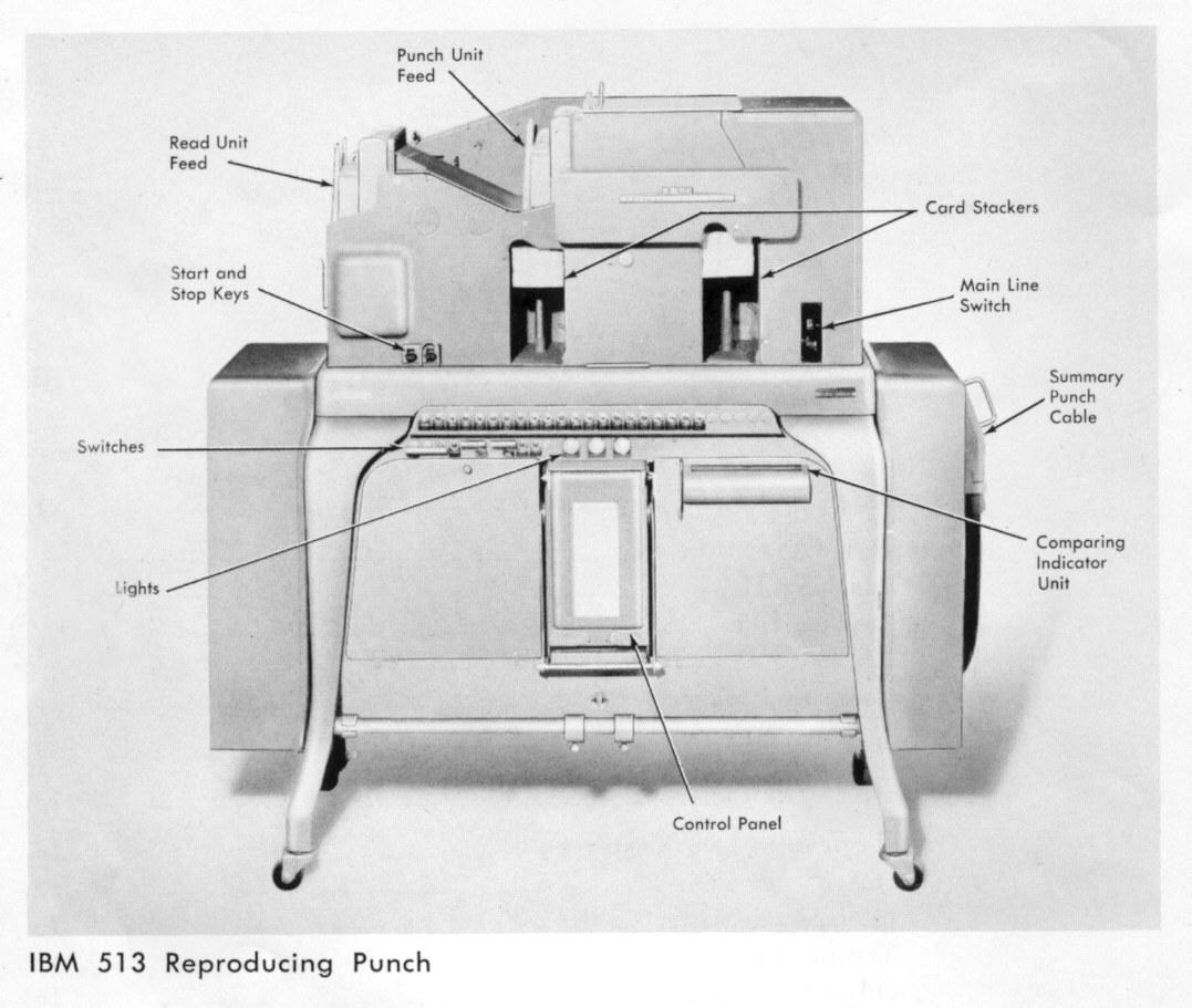
The running speed of this machine was 100 cards per minute. The machine had two card feed units, the Read Unit and the Punch Unit. The two main functions of the machine were:-
1. Reproducing - the copying of data in whole or in part, read from one set of cards to punch into a second set, not necessarily into the same numbered columns from which the reading was made.
2. Gang-punching - punching data read from one card to those which follow it, or until a card is read which signals by designation that it is not to be punched, but may in turn act as a master card for data read from it to be punched into cards which follow. Data may be punched into the same numbered column of the field from which it was read or alternatively offset to another column or field. This is termed Offset Gang Punching.
- The Reading Unit
Cards are fed from the Read Unit hopper with the top edge, that is the "Y" edge leading. On its way to the Read Unit stacker the card encountered three sensing stations, namely:-
1) The "X" Brush station. This accommodated six special brushes known as the RX Brushes. These were not in fixed relationship to the card columns, being designed to be movable to column positions as required. To avoid undue complication at this stage the purpose of the RX brushes will be described later.
2) The Reading Brush Station. This was the second station in the Reading Unit and consisted of 80 sensing brushes for reading card columns 1 - 80.
3) The Comparing Brush Station. The third card sensing station, having 80 sensing brushes to cover columns 1 - 80. After leaving this station the card entered the stacker.
- The Punching Unit
Cards were fed from the Punch Unit hopper with the "Y" edge leading, in phase with cards feeding through the Reading Unit. As with the Reading Unit the Punch Unit had three card stations.
1) The "X" Brush Station This provided for six moveable (to any column position) PX brushes, used for reading "X" designations only. The functions carried out by these brushes are explained later.
2) The Punch Magnet Station. This corresponds in card phasing to the Reading Brush station in the Read Unit and provides for the punching of data in card columns 1 - 80.
3) The Punch Brush Station. This corresponds in card phasing to the Comparing Brush station in the Read Unit and provides for the reading of data in card columns 1 - 80.
- The Plugboard
This was of the interchangeable type, the plugboard design providing for 80 sockets for each of the Reading and Comparing Brush stations in the Read Unit, and similarly for the Punch Magnet and Punch Brush stations in the Punch Unit.
The plugboard also provided for the six Read X Brushes together with an associated socket labelled "RX".
In like manner sockets existed for the six "PX" Brushes and for an associated socket labelled "PX".
- Comparing Relays
Data copied from one card to another, either by reproducing or gang-punching, could be checked by means of the Comparing Relays, of which there were 80.
Each Comparing Relay was represented by two inlet sockets on the plugboard. If both inlets received identically timed card reading pulses, or no pulses at all, the relay remained in its normally stable state, otherwise it triggered stoppage of the machine, together with illumination of a red signal light and operation of a signal arm or arms to point to the error detected relay or relays on a 1 - 80 number scale. It was then up to the operator to take remedial action.
- Arrangements When Reproducing
The cards from which data are to be copied are fed to the Reading Unit for reproducing these data to cards fed to the Punch Unit. The plugboard set-up will be as follows:-
1) The relevant Reading Brushes plugged to the Punch Magnets.
2) The appropriate Comparing Brushes plugged to one set of inlets of Comparing Relays.
3) The Punch Brushes identifying with the Punch Magnets will be plugged to the second inlets of the Comparing Relays which were connected with the Comparing Brushes.
- Arrangements When Gang Punching
Gang punching operations could range from very simple to complex arrangements. For example an unlimited number of cards could be gang-punched with the data held in a single card which headed the file, with the plugboard set to connect Punch Brushes to read the field on the leading card with the Punch Magnets corresponding to that field. A check upon all cards would then be made by sight determination that first and last cards held the same data in the field concerned.
- Use of PX and Punch X Brushes
Consider a number of batches of cards where each batch is headed by a master card, from which data are to be punched into the cards which follow the master card. The master card will carry an "X" hole designation, to be sensed by a PX Brush whose plugboard socket will be plugged to the PX socket. The master card field from which data are to be read will be plugged from the Punch Brushes to the Punch Magnets. Data read from the Punch Brushes will be punched into each following card in turn until the next master card is to arrive at the Punch Magnet station, whereupon the action of PX will be to cause suspension of punching whilst the master card passes the Punch Magnet station.
- Use of RX and Read X Brushes
To check the punching operation of a gang-punching run involving interspersed X designated masters, as cards are taken from the Punch Unit stacker they may be fed to the Read Unit of the machine for checking. The plugboard setting for the check operation requires plugging from the appropriate Comparing and Reading Brushes to Comparing Relays, and for the reading of the master card X designation by a Reading X Brush plugged to RX. The effect will be for each card to be compared with its follower, except in the cycle when the X designated master card arrives at the Reading Brush station.
- Offset Gang Punching
As an example consider a master card punched with the letters A, B, C, ... Z in, say, columns 1 - 26, and that this card is followed by 25 blank cards, then if Punch Brushes 2 - 26 are plugged to Punch Magnets 1 - 25, then with these 26 cards fed through the Punch Unit it can be seen that column 1 of cards 1, 2, 3, 4 ... 26 will record the letters A, B, C, D, ... Z respectively.
An operation based on this principle was used in the daily Enigma tetragraph repeat search processing.
It will be appreciated the offset gang-punching in the manner described is not limited to dealing with monographs, as it can obviously be applied to figure or letter groups.
Checking of data punched by offset gang-punching can of course be checked by transferring cards to the Reading Unit for comparison to be made through readings taken from the Reading and Comparing Brushes .
15 The Collator
| |
Probably the BTM equivalent of the IBM 077 |
This machine operated at a speed of 12,000 cycles per hour, a cycle not necessarily being relative to the passage of one card, but sometimes two, depending upon the process in progress.
The machine had two card feed units, the Primary and the Secondary operating units. It had four card stackers or pockets, these being named from left to right as follows:-
- a) Secondary Select
- b) Secondary Matched
- c) Merged cards
- d) Primary Select
The Secondary Card Feed Unit was situated above the Primary Card Feed Unit, although the card pockets were all in line, on the same level as shown below.
| |
A blank space was left here in the National Archives copy, presumably intended for a diagram to be drawn in. This similar diagram is taken from a 1978 US Navy manual, "Digital Computer Basics". 
|
As the names imply a card feeding from the Primary Feed could have access to either of pockets 3 or 4, whilst a card from the Secondary Feed was destined to enter one of pockets 1, 2 or 3, in accordance with the instructions set by the plugboard programme.
The machine had two Control Units, each to accept and evaluate readings from pairs of cards, to determine whether the two readings were of equal standing or which of the pair was lower than the other, these findings being programmed as required to control distribution of cards to the pockets.
There were two obvious uses for the machine, viz.:-
1) To merge two files of cards to produce a single file in sorted sequence.
2) To divide a sorted file of cards into two separate files, the one having cards in relationship with one other, or many, by virtue of the same readings in the control field, leaving cards without such relationship to enter a second pocket. This arrangement enabled the machine to search for code or cypher text repeats.
The Collator was equipped with three 80 column card reading stations, the Primary unit having two of these stations, the first encountered by a card feeding from the hopper being known as the Primary Sequence Brushes, the next being the Primary Brushes.
The single brush station in the Secondary Unit was of course known as the Secondary Brushes. It will be appreciated that for the operation of merging two files of cards, a Control Unit will be connected to receive readings from the Primary and Secondary Brush stations, whereas for checking the sorted order of a file of cards, or dividing a file into two parts, for example those cards having data in common from those which do not, the Control Unit will evaluate readings from successive pairs of readings from the Primary and Primary Sequence Brushes.
The Primary Sequence Brushes were often utilised when merging two files of cards, since they enabled a sequence check to be made during the merging operation.
The standard Collator did not cater for alphabetical character readings, the Control Units dealing only with numerical data.
However, our resident BTM engineers, Page and Aspinall were able to devise an attachment which made it possible to deal with alphabetical card readings when using the machine for repeat searches, for example in dealing with the daily processing of the Enigma traffic to locate tetragraph repeats between one message and another.
The Collator was also equipped with a card counting device, which could be used to control card feed movements when a given number of cards had been counted.
As an example, the machine could be programmed to allow, say, 24 blank cards to be fed from the Secondary Feed to merge behind each punched master card fed from the Primary Feed, for these combined cards to be used in an "Offset Gang-punching" operation on the Reproducer.
16 The Decimal Cross-footing Multiplying Punch
This was a massive machine weighing perhaps as much as half a ton, we eventually had three to call upon in Hut 7 / Block C.
The result of calculations made were punched to the card from which the input factors were read. The standard machines could be used for calculations such as A x B = C - D = E with the operating speed depending on the type of calculation and the size of the factors. At BP modifications were made to provide for non-carry arithmetic, the machine being mainly used for code group and cypher group differencing, where the output speed was about 500 to 600 cards per hour.
In such work each input card carried a pair of groups, A and B and two calculations were made; A - B = D1 and B - A = D2, both D1 and D2 being punched to the card. The object in calculating both D1 and D2 was in order to obtain the required minor difference, for example if D1 appeared as 5928 then D2 would be 5182, due to the non-carrying arithmetic on which all differencing work was based.
The procedures used to check the calculations, and also the processing involved in producing Difference Tables and Column Differencing is given later in the relevant job descriptions.
17 Group Repeat Search
The employment of Hollerith equipment to process message texts to locate cypher group repeats, between one message and another, was frequently called upon in the early part of the war. The message forms delivered to Hut 7 carried a pencilled identification number (Message number), and had the text groups marked off in ten groups per numbered segment.
Allocation of Hollerith card columns for punching and verifying the master cards was as follows:-
Card Columns Data Field 13-16 Message No. 17-18 Card No. (segment - 00, 01, 02 etc) 20-24 1st group 25-29 2nd group etc. etc. 65-69 10th group
The machining operations were as follows:-
1. The master cards were fed to the Reading Unit of a Reproducer to create the detail cards in the Punch Unit. Only one master card Group field could be used at one time, so that the master cards were run ten times, with a change being made in the plugboard set-up for each run.
The detail cards produced by reproduction from the master cards were of the design given below:-
Columns Field 13-16 Message No. 17-18 Card No 19 Run No. ] see (ii) below 20-24 Group ] see (i) below
- (i) The operator altered the plugboard setup for each of the runs, except the first, so that reproduction was made from columns 20-24 for the first run, from columns 25-29 for the second run, and so on until in the tenth run the Group was reproduced from columns 65-69.
- (ii) The Run No. was gang-punched "0" for the first run, "1" for the second run and so on to "9" for the last run.
2. The detail cards were next sorted on columns 20-24 (21-24, if dealing with 4-digit groups)
3. The sorted cards were next run through the Primary Feed of the Collator with the plugboard arranged to select repeats, i.e. cards with the same cypher groups in the sorted field.
4. The cards selected as repeats were listed on the 405 Tabulator, with a control space separating the print lines of different Groups as shown in the example given below:-
Message No. Position Group 28 10 37169 37 15 37169 12 18 38261 etc.
Note: As explained on Page 12 the standard Collator Control Units were not capable of dealing with alphabetical characters, but with the special attachment designed by our chief engineers for the Enigma traffic processing alphabetical character repeat searches could be undertaken.
The daily Hollerith processing carried out in Hut 7 / Block C in dealing with the Enigma message texts was accorded the highest priority. The requirement was to search through the day's traffic to locate tetragraph repeats occurring between messages.
The teleprinter material was edited in Hut 8 to allocate a message number to each form, and to mark-off the text into segments of five teleprinter groups (i.e. 25 characters), numbering each segment (1, 2 ...) within a message. These edited message texts were then made available to Hut 7 / Block C without delay through-out the day.
- Master Card Punching
Upon receipt of a batch of message forms cards were punched and verified to produce master cards as below:-
Card Columns Data Field Notes 1 - 3 Message No. 4 - 5 Card No. i 6 - 7 Underlap ii 8 - 32 Five groups 33 - 37 Overlap iii
| i | This is given by the Segment No. |
| ii | The underlap is given by the last two characters of the last group in the preceding segment. |
| iii | The overlap is given by the first five text letters of the following segment. |
Card punching and verification of the master cards was carried out immediately the edited message forms were received, by pneumatic tube at intervals throughout the day. Similarly some machine operations were carried out as batches of master cards became available from the Punch Room.
Although dealing with small batches of cards, in this way, was wasteful of machine operator time, as well as affecting machine availability for less important work, it did enable the output results to be made available to Hut 8 in the shortest possible time following their advice that the "cut" was to be made; that the final batch of messages had been made available to us.
The Hollerith processing operations were as follows:-
1. The master cards were fed to the Primary Feed of the Collator to merge 24 blank cards from the Secondary Feed behind each master card.
2. The cards taken from the Collator were fed to the Punch Unit of the Reproducer to gang-punch data from each master card to the following 24 blank cards. The data field in columns 1 - 5 of the master card was plugged to gang-punch into columns 1 - 5, but the data in columns 7 - 37 was plugged to offset gang-punch into columns 6 - 36.
Cards taken from the Punch Stacker were fed to the Read Unit to check the gang-punched data.
With the completion of operation 2 it can be said that the cards held data as below:
Columns 1 - 3 Message No. 4 - 5 Card No. 6 - 7 Underlap 8 - 11 Tetragraph 12 - 16 Overlap
Note:- In the interest of simplification this not the fielding arrangement which was actually used.
3. As cards became available from operation 2 they were fed to a Sorter to carry out a "break-down" sorting operation. For this the machine would be set to read column 8 for a "zone" sort, followed by the numerical component sort to aggregate the cards into 26 sub-sets. It can be understood that at the completion of the zone sort the cards for Y, X, and 0 zones could be distributed to three Sorters for the numerical component sort to be carried out, so reducing the elapsed time for the operation.
4. With all messages to hand and cards generated and dealt with in the breakdown sort, the breakdown batches A, B, C ... Z were shared among several Sorters for sorting on the remaining columns of the tetragraph field.
5. For this operation the sorted cards were presented to the Collators to select the tetragraph repeat cards.
6. The selected cards were then listed on the 405 Tabulator, for the print-out to show:-
Message No. Segment No. (card No.) Underlap Characters Tetragraph Repeat Overlap Characters
In the print-out a control produced line space separated the data printed for each tetragraph repeat from the next as shown below:-
43 LD WUHD GRZL 75 SQ WUHD NYPS 14 IH WVAK RMGM
- The Daily Work Load
It was the case that the daily Enigma traffic gave rise to a total of around 80,000 cypher text characters.
The Hollerith processing in dealing with this material called for slick and expert machine operation, and involved a large number of machines for many of the operations, as can be judged from the notes set out in tabular form below:-
| Operation | No of cards (C) or card passages (CP) |
Hours | |
|---|---|---|---|
| a] | Punching Master Cards | 3,200 (C) | 30 |
| b] | Verifying Master Cards | 3,200 (C) | 30 |
| 1] | Collating blank cards behind each master card |
80,000 (C) | 7 |
| 2] | Offset Gang-punching | 160,000 (CP) | 8 |
| 3] | Breakdown Sorting | 160,000 (CP) | 8 |
| 4] | Follow-up sorting | 240,000 (CP) | 12 |
| 5] | Collate for Tetra repeats | 80,000 (C) | 7 |
| 6] | List repeats | 1,000 (C) | 0.25 |
| 102.25 | |||
The "Cut" instruction from Hut 8 was liable to be made late in the evening, in which case the Team Leader would draft many machines and operators to the work to gain the earliest possible completion. This did not necessarily mean that an operator was needed for each machine pressed into service, because many operators were adept in running two or more machines at the same time.
19 The Window Index of Key Groups
- The requirement
Given pages of a book of Key Groups it was required to show all the groups in numerical sequence, each on a separate print-out line, together with the four groups which preceded and the five which followed the sorted order group. Thus a window of ten group span is formed for each key group to appear in due turn, along with its preceding and following associates.
- The processing procedure
A detail card is prepared for each group in the Key Book, the cards also recording the Page, Line and the position in the line where the group is located.
The cards are then sorted to arrange them in Page sequence, with those for each Page in Line sequence and with the ten cards for each Line in position sequence within the line, i.e. the sorted order of the cards is Page(major) Line (intermediate) and Position in Line (minor).
These cards are then run through the Read Unit of the Reproducer, to reproduce data from them to punch into blank cards feeding from the Punch Unit hopper. For the recording of the key groups these Punch Unit cards should be visualised as having ten fields, 0, 1, 2 ... 9 from left to right.
The Reproducer is programmed for the Group field read from a Read Unit card to punch into field 9 of the phasing Punch Unit card; also fields 1 - 9 of the Punch Unit cards will be read at the Punch Brush station to punch into fields 0 - 8 of the card at the Punch Magnet station.
With this arrangement it can be seen that each card feeding through the Punch Unit is first punched in field 9 with a group read from a Read Unit card, and is next punched in fields 0 - 8 with the groups that the previous Punch Unit card held in fields 1 - 9. So every group in the Key Book is made to enter the window span at the rightmost end and appear in every other position to the left.
As it is in field 4 of the window which is to be used for the sorted order presentation of the Index, the indicative references which are printed must be those relative to the group in that field. In the same way that a key group is copied from its field of entry to the field on the left and passed on embracing ten fields of the card, so provision is made for a similar arrangement to apply for each of the indicative references, Page, Line, and Position in Line which are relative to the group in field 4 of the window span. Thus whereas to deal with the key groups 5 x 10 = 50 columns are needed, the requirements for the indicative data are:-
Page No (00-99) i.e. 2 x 6 = 12 columns Line No. (0 - 9) 6 Position in Line 6
- Operational procedure
- Master cards
A card is punched and verified to record the ten groups of each key page line, using the card design given below.
Card columns Field 17 - 18 Page No. 19 Line No. 20 - 24 Group 0 25 - 29 Group 1 30 - 34 Group 2 etc etc 65 - 69 Group 9
- Machining Operations
1. Reproduce from the master cards in ten runs to produce the detail cards, using the arrangements as below.
Reading brushes Punch magnets 17 - 18 16 - 17 (Page No.) 19 18 (Line No.) 19 Gangpunch Run No. 0, 1, 2 ... 9 Run0 20 - 24 25 - 29 Run1 25 - 29 ,, Run2 30 - 34 ,, etc Run9 65 - 69 ,,
2. Sort the 10,000 detail cards on column 19 (Position in Line) minor, column 18 (Line No.) intermediate, and columns 16 - 17 (Page No.) major.
3. Reproduce from the cards to blank cards fed to the Punch Unit to produce the Window Index cards, using the plugboard set-up given below:-
Reading brushes Punch magnets Punch brushes Page No. 16 - 17 11 - 12 1 - 10 3 - 12 Line No. 18 18 13 - 17 14 - 18 Pos. in Line 19 24 19 - 23 20 - 24 Group 25 - 29 70 - 74 25 - 69 30 - 74
The Window Index cards produced at operation (3) carry the pertinent data in the card columns set out below:-
Columns Field 1 - 2 Page No. ) Indicative 13 Line No. ) references 19 Position in Line ) to Group 4 25 - 29 Group 0 30 - 34 1 35 - 39 2 40 - 44 3 45 - 49 4 50 - 54 5 55 - 59 6 60 - 64 7 65 - 59 8 70 - 74 9
4. The cards are sorted on columns 45 - 49 to produce the Group 4 sequence in which the cards are listed.
5. The sorted cards are listed on the 405 Tabulator, to print 50 lines per page, the print line field sequence conforming to the card field sequence given at (3) above.
20 Positional Double Repeat Search
The process was designed to find messages in common with others by virtue of each having a pair of cypher groups repeated in another, and where the left to right separation of one of these groups from the other was the same in a given pair of messages.
This involves a rather complicated procedure as detailed below.
- Master cards
Master cards were punched with ten groups per card, the first card for a message being punched as card number 00, the second 01 and so on.
The card design is as below:-
Columns Field 13 - 16 Message No. 17 - 18 Card No. 20 - 24 Group 1 25 - 29 Group 2 etc etc 65 - 69 Group 10
- Processing Operations
1. Reproduce from the master cards in ten runs, reading from each of the fields 1, 2, 3 ... 10 in turn, to produce detail cards of the following design:-
Columns Field 53 - 56 Message No. i 57 - 59 Position ii 60 - 64 Group. iii
i Message No. reproduced from master card cols 13 - 16 ii Column 59 gang-punched 0, 1, 2 ... 9 for runs 1, 2, 3 ... 10 with columns 57 - 58 reproduced from master card columns 17 - 18 iii Group reproduced from master card fields 20 - 24, 25 - 29, 30 - 34 etc to 65 - 69 on runs 1, 2, 3 ... 10 respectively.
2. Sort the detail cards into Group sequence - columns 60 - 64
3. Collate the detail cards to select to select cards having identical Groups in columns 60 - 64.
4. Using cards selected at (3) sort on columns 53 - 56 to arrange them in Message No. sequence.
5. The cards sorted at (4) are next run in the Collator with control on the Message field to select repeats. Non-repeats on Message No. are set aside as they obviously cannot contribute further in the search for double repeats.
From this point on it will be helpful to make use of a "toy" example to help follow the further processes. Suppose that the selected cards are as shown below:
Message No. Position Group 17 10 D 17 23 J 18 15 A 18 21 H 19 12 A 19 24 H 23 5 D 23 18 I
6. The cards selected at (5) are fed to the Sorter to sort on the Group field, columns 60 - 64. The "toy" cards would then be in the sequence shown below:-
Message No. Position Group 18 15 A 19 12 A 17 10 D 23 5 D 18 21 H 19 24 H 23 18 I 17 23 J
7. The cards are next run in the Collator to select repeats, controlling on the Group field. Non-repeating cards are set aside leaving the repeats as depicted below:-
Message No. Position Group 18 15 A 19 12 A 17 10 D 23 5 D 18 21 H 19 24 H
8. The cards selected at (7) are now run through the Reproducer to carry out an "Offset-Gangpunching" operation, with the plugboard arranged as below:-
Punch Brushes Punch Magnets 53 - 56 13 - 16 Message No. 57 - 59 17 - 19 Group position 60 - 64 20 - 24 Group
The effect on the "Toy" cards will be:-
Columns 13 - 24 Columns 53 - 64 Message Pos Group Message Pos Group 18 15 A * 18 15 A 19 12 A 19 12 A 17 10 D 17 10 D 23 5 D 23 5 D 18 21 H 18 21 H 19 24 H * The leading card is scrapped
9. The cards from (8) are now sorted on the right hand Message No. (minor) and the left hand Message No. (major) to order the cards as shown below:-
Message Pos Group Message Pos Group 17 10 D 23 5 D 18 15 A 19 12 A 18 21 H 19 24 H 19 12 A 17 10 A 23 5 D 18 21 H
10. In this operation the cards are fed to the Collator with the left and right hand message number fields conjoined in plugging to the control unit of the machine, for comparison to be made between successive pairs of cards, for the selection of those having identical paired message numbers. Thus of the "toy" cards from (9) above selection would be made of those shown below:-
Message Pos Group Message Pos Group 18 12 A 19 15 A 18 21 H 19 24 H
It will have been noted that operation 10 located all double repeats whether positional or not, so that to remove cards for the non-positional repeats further operations need to be carried out. Details of these additional operations now follow:-
11. The cards selected at (10) are next fed to the Collator to select cards which have the left hand Position No. lower than the right hand number. For simplification the cards will be referred to as LL (Low Left) and LR (Low Right).
12. The LL cards are next run in the Cross-Footing Multiplying Punch to subtract the left hand Position No. (columns 17 - 19) from the right hand Position No. (columns 57 - 59), punching the results in a "Separation" field, columns 65 - 67.
13. The LR cards are treated in similar manner as were the LL cards, but to subtract the right hand Position No. from the left hand number.
14. The LL and LR cards are now combined and sorted as specified below:-
Columns 65 - 67 (Separation) minor Columns 53 - 56 (Right-hand Message No.) intermediate Columns 13 - 16 (Left-hand Message No.) major
15. The cards are next run in the Collator with control on the columns sorted at (14), to select repeats.
16. The cards selected at (15) are listed on the 405 Tabulator to print-out the positional double repeats, as in the example below:-
Message No. Pos Group Message No. Pos Group Separation 18 12 A 19 15 A 3 18 21 H 19 24 H 3
21 Production of Difference Tables
Hut 7 / Block C had many orders for producing Difference Tables, especially in the early stages of the war. Much of this type of processing was done for Mr Steve Wills; and among others requiring this processing was Mr W. Bodsworth and Colonel Jacob.
The requirement was for computing the Difference between each and all others of the code groups which had been recovered for a given code, and to make a print-out of these results in Difference order, each print line listing the given Difference together with the pair of groups concerned.
As the number of code groups involved was generally not large the initial key punching of master cards was of small account. But even so a relatively small number of groups could result in a large number of pairings of each group with all others. Given N groups then the number of pairings is given by 1/2 N x N-1 for example, for 100 groups the number of differences to be found is 4,950.
- The Hollerith Procedure
In this description it will be convenient to use a "toy" example, dealing with six code groups, 1, 2, 3, 4, 5 & 6, each to be differenced with the others.
1. Master cards would be punched, each with two fields A and B to record each group in turn in (A) with the following group on the list in (B), as shown in the example below:-
A B 1 2 2 3 3 4 4 5 5 6
2. These cards were reproduced with field B read by the Reading Brushes as normally, but field A was read for reproduction by the Comparing Brushes. So the initial card produced in the Punch Unit had no punching in field A, the overall effect being as shown below:-
Punch Unit cards Read Unit cards A B A B - 2 1 2 1 3 2 3 2 4 3 4 3 5 4 5 4 6 5 6
Now if we scrap the first card taken from the Punch Unit and re-feed the remainder to the Read Unit to reproduce from these we shall obtain a further set of pairings, viz:-
A B - 3 1 4 2 5 3 6
The process continues in this way, with cards taken from the Punch Unit transferred to the Read Unit, until the last pairing is made in the Punch Unit from the two final cards which are entered to the Read Unit.
3. In this operation all cards were fed to the Decimal Cross-footing Multiplying Punch to compute two differences where D1 was the result of Group A minus Group B, and that of D2 Group B minus Group A, all arithmetic being without carrying, with the pair of differences punched into the card from which the input factors were read.
4. To check the calculations the cards were run through the E6/6 Tabulator, for the digital values in fields A, B, D1 and D2 to be summed in the non-carry counters 1, 2, 3 and 4 respectively. After addition had taken place from between 100 and 200 cards, the operator would stop the machine in order to read off the counter wheel readings, visible through the counter windows. After checking that the total held in counter 3 was equal to the content of counter 1 minus that in counter 2, and in like manner that the reading in counter 2 minus that in counter 1 would produce the result in counter 4, the operator would restart the machine to check the next batch of cards. In the rare event of error detection the batch of cards in question could be listed on the tabulator to pin-point the error card for replacement.
5. It will be appreciated that for any one of the cards, either of the two fields, D1 or D2 might be recording the minor difference between Groups A and B, whereas it is required in the concluding operations that the minor difference will be held in field D1. To achieve this two operations were necessary, the first to segregate those cards in which the minor difference was held in field D2. This was done by passing the cards through the Primary Feed of the Collator to compare fields D1 and D2 to select cards having the minor difference in field D2, such cards entering the Primary Select pocket. (The Secondary Feed would serve just as well so the task could be shared between the two units of the machine, the Secondary Select pocket serving to receive cards which would otherwise have homed in the Primary pocket.)
6. All cards having the minor difference in field D2 were reproduced to make a replacement set having the appropriate interchange of data fields. The original cards were set aside for destruction; the replacement cards being used in the next operation together with those found acceptable at (5) above.
7. To prepare for printing the Difference Table the cards were sorted into Difference order on the D1 field. The cards were then listed on the 405 Tabulator to present the data as indicated below, printing 50 lines per page.
- Group A - Group B - Difference - Thumb Reference
The thumb reference consisted of three high order digits of the Difference. The thumb reference was printed to the extreme right hand edge of the page, so that the operator had to ensure that the smallest degree of paper creep did not occur.
Mr Steve Wills was most particular about this to ensure that his Difference look-up speed was not impaired. I and others were delightedly impressed to see his dexterity in using the product of our labours, his left hand holding the pages as a whole, yet his thumb free and poised to release the pages to flash past his gaze until arrested by the appearance of the reference he sought.
Whilst working with the Difference Table, for use in key finding for the columns of his message depth sheet, his left hand was never free, nor was his right hand, with pencil held at the ready for group decypherment. Steve Wills was one of our most favoured customers.
22 Index of Column Differences
The calculation and presentation of Column Differences was in some ways similar to the production of a Difference Table, but was a more involved and complicated procedure.
For Hut 7 / Block C to produce listings of Column Differences the cryptanalyst supplied his message depth sheet. This large form (about 24 x 15 inches as I remember it) was ruled into, say, 40 vertical columns and perhaps 20 ruled horizontal lines. Data written into any one line stood as the cypher groups of a message wherein one or more of the message cypher groups had been found to be identical with a cypher group, or groups in some other message. The pair of message texts 1inked in this way were written out at offset to locate the like groups in the same column of the depth sheet.
This arrangement was based on the possibility that the common cypher groups might have derived from the same code group encyphered by a common key. Then if the difference between a pair of cypher groups within the Depth Sheet column was the same as that to be found in the Difference Table of known code groups, the encyphering key group could be deduced, enabling this key to be used to decypher all groups within that column of the Depth Sheet. It was this line of attack which required Hut 7 / Block C to evolve the procedures for Indexes of Column Differences, about to be described.
- The Hollerith Procedure
This in part is of course similar to the processing for the production of a Difference Table, which has already been described, but whereas a Difference Table might well contain 5,000 differences formulated from a hundred or so code groups, a message depth sheet, with its many columns might have only a few groups in each. Thus if each column of groups were to be processed separately in the same way as for a Difference Table the proceedings would be tedious in the extreme. For this reason the following procedure is used:-
1. Initial punching of cards
A card is punched for each successive pair of groups in a column of the Depth Sheet. For example, given groups A, B, C and D in depth, three cards would be punched, A/B, B/C, and C/D. The card for each pair of groups has five fields as shown below:-
1) Depth Sheet Column No. 2) ,, repeated 3) Depth Sheet Line No. 4) Group 1 e.g. A 5) Group 2 e.g. B
These cards represent the first pairing of groups for differencing and will be used to generate cards for the second pairing, the second pairing cards producing those for the third, and so on, as shown in the examples below:-
2. First pairing cards
| Fields | 1 | 2 | 3 | 4 | 5 |
|---|---|---|---|---|---|
| Col(a) | Col (b) | Line | Grp 1 | Grp 2 | |
| 1 | 1 | 1 | A | B | |
| 1 | 1 | 2 | B | C | |
| 1 | 1 | 3 | C | D | |
| 2 | 2 | 1 | E | F | |
| 2 | 2 | 2 | F | G | |
| 2 | 2 | 3 | G | H | |
| 2 | 2 | 4 | H | I | |
| 3 | 3 | 1 | J | K | |
| 3 | 3 | 2 | K | L | |
| 3 | 3 | 3 | L | M |
(Note: the purpose of the repeated column number in field 2 is to prevent pairing of groups from different columns, as will be seen later.)
3. Second pairing of cards.
The Reproducer is used to reproduce data from the 1st Pairing cards, with data read from the Reading Brushes for fields 2, 3 and 5 but with data read from the Comparing Brushes for fields 1 and 4. The 2nd Pairing cards produced in the Punch Unit will be as shown below:-
1 2 3 4 5 Col Col Line Grp. 1 Grp. 2 - 1 - - B 1 1 1 A C 1 1 2 B D 1 2 3 C F 2 2 1 E G 2 2 2 F H 2 2 3 G I 2 3 4 H K 3 3 1 J L 3 3 2 K M
However, of the cards produced in the Punch Unit those which do not have identical Column Nos in fields 1 and 2 are unwanted, because they carry pairings of groups from different columns. To deal with this cards taken from the Punch Unit are fed through the Collator to select cards where the content of fields 1 and 2 is not identical, leaving non-selected cards to be used in the Reproducer to generate the 3rd Pairing cards.
Proceeding in this way the completion of all required Reproducer pairing runs is signalled when cards presented to the Collator are all selected as erroneous pairings. This arrangement automatically deals with some Depth Sheet columns containing fewer groups than others, as well as signalling the end of the pairing process.
The remaining operations which have to be done are similar to those used for production of a Difference Table, but in brief the further operations are as follows.
a) Compute the non-carry difference for Group 1 minus Group 2 = D1. also Group 2 minus Group 1 = D2, using the cross-footing facility of the Multiplying Punch.
b) Check the calculations using the E6/6 Tabulator.
c) Using the Collator, select cards having the minor difference in field D2.
d) Reproduce cards selected at (c) to make replacement cards with interchange of Group 1 and Group 2 fields as well as interchange of D1 and D2.
e) Combine cards produced at (d) with the non-selected cards from (c) and sort the combined cards on field D1 as a minor order sort, with a major order sort on the Depth Sheet Column No. field.
f) The sorted cards will then be listed on a 405 Tabulator to provide a print-out as indicated below:-
- Column No. Group A Group B Difference.
23 The Work Range and Personnel
What has been written in the preceding pages was set down with two aims in mind:-
a) To give a brief description of each of the various types of Hollerith machines used at Bletchley.
b) To give some idea of how the machines could be used in concert to achieve a specific result of the type required in Bletchley Park.
A point of note is that only five procedures have been described and these can be regarded as standard work items. We had many other standard procedures to hand, but a large proportion of the work carried out was on the once only basis, which called for special operating procedures to be devised.
Some of these special procedures were required to be prepared for Brigadier Tiltman. He made a point of returning to us following the successful outcome of his labours, so that he could personally thank the operators for the work they had done for him. Also he always made light of his break-in into the cypher, sometimes saying that he didn't quite know how he had done it; that he had just had a "hunch" and found that it worked. It was always a great pleasure working for him.
Of course, some processing started as a special procedure and then became a standard item in our repertoire. In other cases a special job routine needed to be devised solely for one specific task. An example of this dealing with Playfair decyphering. Another was in producing a so-called Hagelin Catalogue, the Hagelin machine being used by the Italians. This became a regular monthly task, demanding an all-out team effort for timely completion. Unfortunately I cannot remember the details, except that it was a very large job, and quite complicated, requiring a large number of operators. It was the only job where we found it necessary to lay down chalk lines on the machine room floor to ensure correct sequence movement of boxes of cards to the various machines involved.
Among the many visitors to Hut 7 who required new work to be undertaken were the following:-
| Josh Cooper | Joan Clark |
| Shaun Wylie | Wilfred Bosworth |
| Hugh Foss | Hugh Alexander |
| Peter Twinn | Gordon Welchman |
| Colonel Jacob | Steve Wills |
| Henry Dryden | Richard Pendered |
| Alan Turing | Leslie Yoxall |
| Leonard Hooper | Philip Howse |
| Michael Crum | Dr G.W. Morgan |
| Jack Good |
There was also Mrs Winterbotham whom we never saw, although she sent material for processing from her office in Broadway.
24 The Visit of Winston Churchill
By the time of Churchill's visit to Bletchley Park Hut 7 had become a commodious erection as compared with the modest Hut in which we had started our activities. Being a wooden structure it had been comparatively easy for workmen to tear down walls and partitions, and to tack on extensions, not once but several times, until eventually for a time we had ample accommodation for machines and operators. With such a stage to hand, Freeborn, who apart from his very high technical and administrative abilities was always a showman and an opportunist, planned a memorable demonstration of the use of Hollerith equipment in Bletchley Park on the occasion of Churchill's visit to Hut 7.
Freeborn's secretary, Miss Ellen Ford and I were waiting with Freeborn by the entrance door when Churchill strode down the path towards us, followed by three no-nonsense looking men, who were obviously his bodyguard. As Churchill entered the hut his bodyguards attempted to follow, but Churchill rounded on them and in a voice which would have done credit to that of the great huge bear, rasped "Not you", causing them to stop dead in their tracks.
On entering the Machine Room area on his exit from the Key Punching Room, the visitor was presented with a scene of intense activity. There were about 45 machine operators in action and as many or more than that number of machines. Then all the machines were halted at the same instant, and in the complete silence which followed an introductory explanation was given to the visitor as the party stood on the threshold of the area. Then as he was conducted towards a group of twelve or more Sorters, all these machines started into action at the same moment. They were allowed to run only for a short time, and all came to rest as one, so that their function and application could be explained without distraction.
Moving from the Sorters to the Reproducers the same arrangement held; all in action on his approach, but at rest for an explanation to be given by Freeborn, the same arrangements applying for each of our various equipments.
At the conclusion of the demonstration all machines were brought into action as the visitor was conducted to the exit, but all brought to rest as he paused on the threshold as he made his farewells. But on reaching the door he turned back, first to stub out his cigar in a nearby ashtray, and then to turn to Miss Ford, to shake her hand and bid her Goodbye.
Miss Ford had a dazed look as she stared at the hand that the great man had held, then she took up the cigar butt and said it was something she would always treasure.
Of course, another memorable day was when we were able to commence our move from Hut 7 into the purpose designed large brick building - Block C - to be used exclusively for Hollerith processing.
25 Drayton Parslow
Freeborn, my brother and I, remained on the B.T.M. payroll throughout the War, and during this time I was Freeborn's chief assistant and his deputy.
In forming arrangements for B.T.M. personnel to be seconded to B.P., the Company funded living accommodation for the B.T.M. party. A picturesque country house (The Horseshoes) was rented in the village of Nash for the accommodation of Mr and Mrs Freeborn, my wife and I and my brother, Norman Whelan.
Later on, when she left school, Freeborn's daughter joined the Nash household and also the working team in BP as also did Freeborn's secretary, Miss Ford.
After a few months the B.T.M. party vacated the house in Nash, moving to another, The Lodge in Drayton Parslow, again on rental to B.T.M.
The Lodge had extensive grounds, which included a large courtyard around which were numerous stables, saddle rooms and an enormous barn, with paddocks beyond, the owner having previously run a racehorse training establishment.
Some time later, at Freeborn's instigation with the authorities building operations were commenced in the courtyard area and the paddock. The barn was demolished and a machine room built on its site, linking with the stables which were converted as an extension to the machine room and also providing for offices. To complete the building arrangements a large hostel was built in the paddock area.
A battery of Hollerith equipment was installed in the machine room area and additional operating staff were recruited and trained. The operators were housed and catered for on site within the hostel.
Drayton Parslow processing operations were run on a two shift system. The equipment was used exclusively for the compilation of cryptographic material, including One Time Key Pads, Typex settings and so on.
In some cases and from time to time interchange of operators took place with those working at Bletchley. This separate establishment at Drayton Parslow meant that we in the house party had the opportunity of putting in extra hours there in the evening, as well as our normal day-time activities in Bletchley Park.
No doubt this development in the use of Hollerith equipment for production of Comsec material stemmed in large measure from Commander Travis, the Director of B.P., who bad previously been associated with communications security affairs.
It is also the case that Commander Travis made many visits to Hut 7, and had long discussions with Freeborn, in whom it seemed he placed the utmost confidence.
26 Conclusion
My memory fails me when I try to recall the exact number of machines, operators and maintenance engineers to serve Bletchley Park and Drayton Parslow at the peak of our labours, but it would not be far out to say that the total number of people involved in the Hollerith processing areas was to the order of 500. Our consumption of Hollerith cards was 2,000,000 per week.
| |
On the basis that a single card weighs approximately 1/10 oz., that implies that the Hollerith operations consumed around 6 tons of card stock per week. It is hard to imagine how the logistics of this were managed given war-time shortages of fuel and paper. |
I am pleased to be able to conclude by reporting that Freeborn was awarded an O.B.E. for his contribution to the war effort.
| |
Frederic Victor Freeborn (28 Jan 1897 - 29 Mar 1977) was awarded an O.B.E. in the New Year's Honours List of 1945. Ronald Whelan was himself awarded an M.B.E. in the Queen's Birthday Honours List of 1974. |
In the various books recently published which deal with the war-time activities carried on at B.P. Freeborn's outstanding contribution is ignored.
He was, in fact, the outstanding expert in the field of Hollerith data processing at that time, as well as possessing great organising ability, which he displayed to the full in building up the Hut 7 / Block C organisation.
No-one else could have produced the outstanding contribution which the Hollerith machinery gave to B.P. through-out the war years.
At the end of the war with the setting up of G.C.H.Q. it was proposed that a Hollerith installation should be included in the organisation, together with the personnel who had worked under Freeborn at Bletchley, and who might wish to continue in this type of work. To be able to do so the staff to be used were to become Civil Servants, providing those wishing to take this step were judged to be suitable to take up appointments.
In view of the numbers involved it was decided that only Freeborn and I should appear before the Civil Service Commissioners, and if we were judged acceptable those who had worked with us would also be accepted. I am pleased to say that those who wished to do so duly became Civil Servants.
I am also pleased to make known that at my interview my "Prisoner's Friend" was none other than Widow Twankey, alias Frank Birch.
Frank Birch was Head of the Naval Section at B.P. and we in Hut 7 found him to be a delightful jovial character. It was said that he had appeared on the stage in pantomime, playing the part of Widow Twankey.