Difference between revisions of "Enigma/Paper Enigma"
m (→The Plug Board) |
(→Acknowledgements: Reference to the 2005 cipher challenge, thanks to "Harry" for pointing this out!) |
||
| Line 113: | Line 113: | ||
UK company [http://www.mindsetsonline.co.uk/about_us.php Mindsets] sells an [http://www.mindsetsonline.co.uk/product_info.php?products_id=1228 Enigma kit] consisting of cut-out-and-glue paper cylinders wrapping around pieces of drainpipe. Although this form factor is very useful for teaching people about the operation of a real Enigma machine, their design is not compatible with one, as there is no reflector and the rotor connections are shorter than the real thing. | UK company [http://www.mindsetsonline.co.uk/about_us.php Mindsets] sells an [http://www.mindsetsonline.co.uk/product_info.php?products_id=1228 Enigma kit] consisting of cut-out-and-glue paper cylinders wrapping around pieces of drainpipe. Although this form factor is very useful for teaching people about the operation of a real Enigma machine, their design is not compatible with one, as there is no reflector and the rotor connections are shorter than the real thing. | ||
| + | |||
| + | The 2005 [http://www.cipherchallenge.org/ British National Cipher Challenge], run by the University of Southampton, featured a crisp-tube [http://github.com/themaddoctor/BritishNationalCipherChallenge/blob/master/2005/8B/Pringleupdate.pdf paper cipher machine design] approximating the Russian [http://en.wikipedia.org/wiki/Fialka Fialka] rotor machine. This includes the neat feature of using the tube cap as the reflector. | ||
Revision as of 20:27, 6 August 2019
Although the Enigma cipher as a whole is quite complex (it's complexity is comparable to modern cryptographic algorithms) the individual transformations within it are relatively simple. In fact, they are simple enough that you can decipher an Enigma message with just a paper model.
Our model is three-dimensional, to illustrate the wiring of a real Enigma machine. It needs only common household items to construct, and is completely compatible with all settings of a real Enigma machine (models I, M1, M2 and M3).
Contents
Materials Needed
You will need these PDF templates printed on to 2 A4 sheets of paper, a crisp tube (75mm in diameter and at least 225mm long), clear sticky tape and a pair of scissors.
Using low-tack "removable" sticky tape can make it easier to swap round and reuse the rotors if you want to do that, but it's not essential.
Before you print the templates, please make sure you turn off any scaling options in your printer software so that it is printed at the exact size required. Scaling may be set to "Fit to printable area" by default; you should set it to "None". The templates use colour to help you follow the lines, but this is not essential and you can print them in black-and-white if you like.
Assembling the Basic Enigma
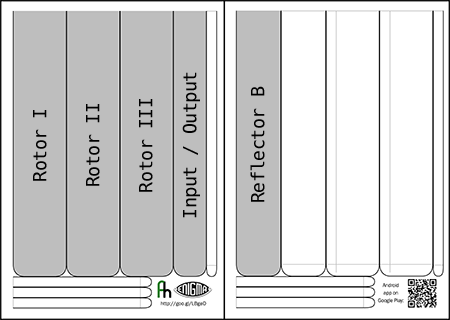
You can start with the basic Enigma machine (using three rotors with ring settings of 01 01 01) using just the 5 pieces shaded in this diagram:
You will fasten these round the crisp tube in this order, from left to right:
- Reflector B, Rotor I, Rotor II, Rotor III, Input/Output
Now, starting with the rounded end, wrap the paper piece around the tube and stick it to itself, covering the rounded end.
Wrap the reflector and input/output pieces tightly as you do not want those to move during your enciphering; putting the rotor pieces on a bit looser will make them easier to turn.
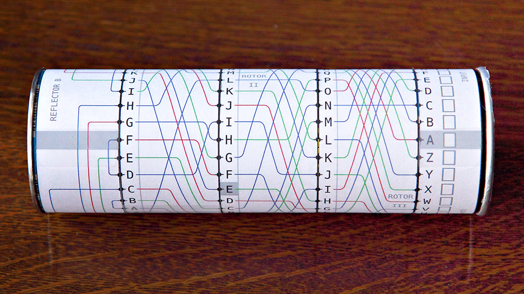
You should end up with something looking like this:
Using the Basic Enigma
Set up:
- Make sure that the grey bars on the Reflector and the Input/Output cylinders line up; this shows the start position of your Enigma machine and lets you track the turnover positions of the rotors.
- Turn the rotors so that the three letters of your message key are in line with the grey bars; for practice use A B C.
For each letter in your message:
- Turn just the right-hand rotor one step towards you (so the letter in line with the grey bar becomes the next one alphabetically); make sure that the other rotors and the Input/Output cylinder stay still. You must do this before you read off the letter (even the first one!)
- Find the letter from your message on the Input/Output cylinder at the right-hand side, and trace the line from it through all three rotors, in to the reflector, out again back through all three rotors and into the Input/Output cylinder again. Write down the letter at which you end up.
For practice, try this message:
- A E F A E J X X B N X Y J T Y
If you got it right, you should have written down one correct English word!
Rotor Turnover
When the right-hand rotor turns one step, at some positions other rotors turn over as well, which makes the scrambling harder to predict. In the example above we chose the message key A B C with a short message so that no turnovers occurred.
To handle turnover correctly, we need to add to our instructions above for turning the rotors, based on the letters showing in line with the grey bars:
- If the letter on the middle rotor is shaded grey, turn all three rotors one step towards you,
- otherwise, if the letter on the right-hand rotor is shaded grey, turn the middle and right-hand rotors one step towards you,
- otherwise, turn just the right-hand rotor one step towards you.
The shading of the letter on the left-hand rotor doesn't matter; it would only come in to play if that rotor was in a different place in the order.
For practice, try deciphering this message with the rotors in the same order as our basic example above (I, II, III) and with message key A B R:
- M A B E K G Z X S G
When you've finished, you should have written down two correct English words, and your rotors should finish at positions A C B.
Double Stepping
Because of the above turnover rules, if the middle rotor steps so that its shaded letter moves into the start position, it must step again (along with the other two rotors) when the next letter in the message is processed. This is called the "double stepping" behaviour and is often misunderstood. To try this yourself, use rotors I, II and III with message key A D S to decipher this message:
- R Z F O G F Y H P L
You should end up with two correct English words, and your rotors at positions B F C.
Ring Settings
On a real Enigma machine, the position of the letters (and the turnover points) on each rotor could be changed by pressing out a pin and rotating the outer ring relative to the position of the wiring inside the rotor. This was part of the machine settings that changed on a daily basis, making the messages harder to crack.
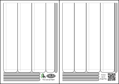
You can represent ring settings on our paper model by cutting out the ring templates, shaded in this diagram:
Note that the rings for rotors III, IV and V are printed in two parts due to lack of space on the page; you may find it easiest to tape the two halves together as a block (so the letter N on each ring joins on to letter M on its other half) before separating the individual rings.
Keeping the rotors I, II and III that you put on for the basic machine, put rings I, II and III over the top of the letters on the rotors. Just tape the ring to itself so it can still move over the top of the rotor; and make it snug so it stays in the same place relative to the rotor when the rotor is turned.
You apply the ring settings by turning the ring around the rotor so that the setting letter is covering the letter A on the rotor underneath (you can move the ring sideways over the rotor temporarily to see what's underneath). When the ring settings are given as numbers, the letter over A for each setting is as follows:
| Setting | 01 | 02 | 03 | 04 | 05 | 06 | 07 | 08 | 09 | 10 | 11 | 12 | 13 | 14 | 15 | 16 | 17 | 18 | 19 | 20 | 21 | 22 | 23 | 24 | 25 | 26 |
| Letter | A | B | C | D | E | F | G | H | I | J | K | L | M | N | O | P | Q | R | S | T | U | V | W | X | Y | Z |
Using rotors I, II and III as before, place the ring settings at 10, 14 and 21. Then turn the rotors to set the message key to X Y Z (the letters showing on the rings, not the letters underneath them) and decipher the following message:
- Q K T P E B Z I U K
As before, the result should be two correct English words.
The Plug Board
The final component that we need to be fully compatible with a real German army Enigma machine is the plug board. The German military added this when they adapted the commercial version of the Enigma machine for their own use, and it improves the security a lot. Twenty-six sockets on the front of the machine (one for each letter) can connect together in pairs with jumper cables. If a letter has no connection to it, it passes through unchanged. Any two letters connected together swap with each other before being passed through the machine and then swap back again for output. There were different numbers of connections used at different times, but the later standard was ten.
To represent this in our model, we need to write in the jumpered letters on our input/output cylinder. If you use a pencil, you can rub them out afterwards and reuse the cylinder (it helps if you used matte-finish sticky tape, as that's easy to write on and rub out). For each letter that is jumpered, write the paired letter in next to it. For example, if D and Q are paired, write D next to Q, and Q next to D. Do this for all the jumpered pairs, and then for the rest of the letters which have no plugs in, write the letter next to itself.
The enciphering and deciphering process is the same as before, except you start tracing the line from where you wrote the letter from your message, and you read off the letter you wrote at the place where you finish tracing the line.
To try this out, write in the plug board settings for these 10 pairs:
- AP BR CM FZ GJ IL NT OV QS WX
Using rotors I, II and III with ring settings 10, 14 and 21 from our previous example and message key V Q Q decipher the following:
- H A B H V H L Y D F N A D Z Y
Your result should be four English words and your rotors should finish at positions V R F.
Version History
30 May 2012, version 1.1
- Use 3 colours for rotor wiring to make parallel lines easier to follow
- Reduce size of input / output cylinder to fit on shorter 165g crisp tube
- Rearrange templates so they can be also be printed on US Letter paper
Acknowledgements
Alan Turing, in his World War II Treatise on the Enigma described a model using what he called Comic Strips. Separate slips of paper represent each rotor and they slide across a flat sheet of paper representing the fixed parts of the machine. Turing's model can encipher any message with exactly the same results as a real Enigma machine.
In 2003, Mike Koss published a simplified Comic Strips model. In 2004, Gary Shannon independently developed a model using cardboard cylinders. Neither of those models included ring settings, and Gary Shannon's model didn't include rotor turnover points, so they are not completely compatible with the real thing.
UK company Mindsets sells an Enigma kit consisting of cut-out-and-glue paper cylinders wrapping around pieces of drainpipe. Although this form factor is very useful for teaching people about the operation of a real Enigma machine, their design is not compatible with one, as there is no reflector and the rotor connections are shorter than the real thing.
The 2005 British National Cipher Challenge, run by the University of Southampton, featured a crisp-tube paper cipher machine design approximating the Russian Fialka rotor machine. This includes the neat feature of using the tube cap as the reflector.


